Osaka, Japan - Panasonic Corporation today announced that it has developed a loop heat pipe (LHP) cooling system equipped with the company’s unique Jet Explosion Stream Technology[1] (JEST), which uses a high-speed jet stream[2] generated by the rapid expansion of the refrigerant which significantly enhances the cooling performance.
Using this technology, the heat pipe[3] has become ready for heat density[4] of up to 390 W/cm² (results from internal experiments[5]). This cooling system can be applied to equipment such as power semiconductors for power conversion systems and supercomputer processing units, where the heat density is expected to rise.
Effects
The high performance cooling at a density of up to 390 W/cm² has been achieved by applying the technology of generating a high-speed jet stream created by the expansion of the refrigerant. This is about 2.3 times the heat density that can be cooled by existing heat pipes, allowing for cooling systems smaller in size and higher in performance. In addition, this system does not require a drive unit to circulate the refrigerant, contributing to energy saving of the target equipment.
Features
The developed cooling system has the following features.
- High performance cooling at a heat density 2.3 times that of heat pipe type makes it possible to reduce the size of the heat receiving section
- Capable of long-distance heat transfer without using a pump or other drive unit to circulate the refrigerant, contributing to energy saving
Technologies
The developed JEST type LHP cooling system (JEST type LHP) has been achieved by the following new technologies.
- High-speed jet stream generation technology using the rapid expansion of the refrigerant
This technology optimizes the shape of the surface subjected to heat from the heat source and the refrigerant supply system, and uses the high-speed jet stream generated by the expansion of the refrigerant to efficiently dissipate heat from the heat receiving surface. - Technology for automatically supplying refrigerant to the heat receiving section
This technology optimizes the difference in pressure before and after the check valve and the hydraulic head pressure[6], which are determined by the pipeline resistance and the volume of refrigerant in the cooling system, according to the amount of heat generated.
Background
Heat pipes have been used for cooling small electronic equipment; however, the amount of heat transported per pipe has been limited, making it unavoidable to increase the size of the equipment in order to deal with the rise in the amount of heat generated.
Cooling systems using a pump to forcibly circulate the refrigerant can respond to the rise in the amount of heat generated by increasing the flow rate of the refrigerant to be circulated in the heat-generating section. However, the power consumption of the pump also increases. In line with the prediction that heat generated by electronic equipment will increase, there has been a rising demand for energy-efficient cooling systems capable of responding to the increase in the amount of heat generation without increasing the equipment size.
Patents
32 applied in Japan (incl. 1 patented), 4 applied overseas
Details of the features
1. High performance cooling at a heat density 2.3 times that of heat pipe type makes it possible to reduce the size of the heat receiving section
 |
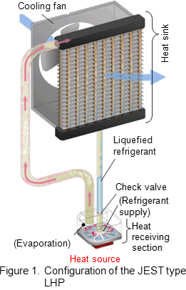
Figure 1 shows the basic configuration of the JEST type LHP. An evacuated looped pipe is filled with refrigerant. The heat radiation section is located above, and the heat receiving section is located below. The check valve is installed at a specific location in the pipe to regulate the one-way refrigerant flow from the heat radiation section to the heat receiving section. The cooling system repeats steps (1) to (3) shown below.
(1) Heat from the heat source evaporates the refrigerant.
(2) The evaporated refrigerant is condensed to liquid at the heat radiation section.
(3) The liquefied refrigerant accumulates above the check valve and is supplied to the heat receiving section according to the relationship between the difference in pressure before and after the check valve and the hydraulic head pressure.
|

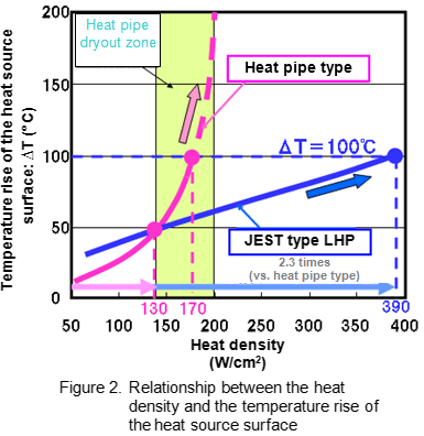
Figure 2 shows the results of our experiment for comparing the JEST type LHP and a cooling system using a conventional heat pipe (hereafter referred to as the heat pipe type) in terms of the relationship between the heat density and the temperature rise (ΔT) of the heat source surface. For example, when the ambient temperature is 50°C and the guaranteed maximum operating temperature of the power semiconductor is 150°C (temperature rise ΔT = 100°C), the maximum allowable heat density for the heat pipe type is 170 W/cm², and that for JEST type LHP is 390 W/cm². However, the graph of the heat pipe type shows a sharp temperature rise from around 130 W/cm², obviously indicating a dryout[7] state. Therefore, the actual manageable heat density for the heat pipe type is a maximum of 130 W/cm².
This indicates that when the heat receiving surface area is identical, the JEST type LHP has a cooling performance equivalent to about 2.3 times the performance of the heat pipe type. In addition, evidence of the dryout state of the heat pipe type shown from around 130 W/cm2 is not visible in the graph of the JEST type LHP at all.
As shown in these comparison results, the JEST type LHP is ready for higher heat density than conventional cooling systems, and can respond to the rise in the amount of heat generated by electronic equipment without increasing the equipment size.
With regard to the heat pipe type, since the amount of heat transported per pipe is limited, it is necessary to increase the number of heat pipes in order to respond to the rise in the amount of heat generated. This makes increasing the size of the heat receiving section unavoidable.
As compared with these types, the manageable heat density for the JEST type LHP is higher, allowing a smaller heat receiving section to provide a similar level of heat treatment performance.
2. Capable of long-distance heat transfer without using a pump or other drive unit to circulate the refrigerant, contributing to energy saving[8]
The forced refrigerant circulation type uses a pump to circulate the refrigerant. When the amount of heat generated increases, the power to drive the pump rises in order to increase the volume of the refrigerant circulated for cooling. Also when the distance between the heat receiving section and the heat radiation section becomes longer, the power required to drive the pump rises because the heat transport distance increases.
The JEST type LHP is a type of natural refrigerant circulation cooling system, which uses gravity to circulate the refrigerant, therefore, it requires no pumps or other external power. The use of a high-speed jet stream allows for heat transport over a distance up to 3 m (results from internal experiments[9]). Such a long-distance heat transfer is available with lower energy consumption than with the forced refrigerant circulation type.
Details of the technologies
1. High-speed jet stream generation technology using the rapid expansion of the refrigerant
This technology optimizes the shape of the surface subjected to heat from the heat source and the refrigerant supply system, and uses the high-speed jet stream generated by the expansion of the refrigerant to efficiently dissipate heat from the heat receiving surface.
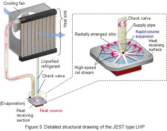
Figure 3 shows the detailed structural drawing of the JEST type LHP. The heat receiving surface has radially-arranged slits. The liquefied refrigerant is supplied through the pipe to the center of the heat receiving surface, and part of the refrigerant removes heat from the heat receiving surface when it evaporates. The evaporated refrigerant rapidly expands, becomes a high-speed jet stream when passing through the small gap between the pipe and the heat receiving section, and spreads peripherally. The jet stream flows at a high speed along the slits on the heat receiving surface, drawing with it the remaining refrigerant that is not boiled. This jet stream flow accelerates the refrigerant evaporation, enhancing the efficiency at which heat is removed from the heat source.

2. Technology for automatically supplying refrigerant to the heat receiving section
This technology optimizes the difference in pressure before and after the check valve and the hydraulic head pressure, which are determined by the pipeline resistance and the volume of refrigerant in the cooling system, according to the amount of heat generated.
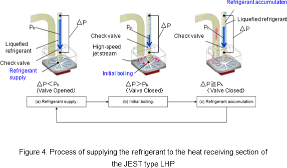
Figure 4 shows the process of supplying refrigerant to the heat receiving section of the JEST type LHP. The difference in pressure before and after the check valve (ΔP in the figure) acts to close the valve. The hydraulic head pressure of the liquefied refrigerant accumulating above the check valve (Ph in the figure) acts to open the valve.
The process steps (a) to (c) below are repeated to supply the refrigerant to the heat receiving surface.
When the difference in pressure (ΔP) becomes smaller than the hydraulic head pressure (Ph) as a result of step (c), the process returns to step (a), supplying the refrigerant again. As shown in this process, the check valve operates according to the balance between the difference in pressure before and after the check valve determined by the amount of heat generated (ΔP) and the hydraulic head pressure of the accumulated liquefied refrigerant (Ph). Therefore, the refrigerant can be automatically supplied to the heat receiving section by optimizing the pipeline resistance and the volume of refrigerant in the cooling system.

Glossary and annotations
- [1] JEST: Abbreviation for Jet Explosion Stream Technology
- Unique name of our technology to accelerate the refrigerant evaporation on the heat receiving surface using a high-speed jet stream generated by the rapid expansion of the refrigerant.
- [2] High-speed jet stream
- It was confirmed that the JEST type LHP generates a jet stream with an average speed of 68.8 m/s when the heat density is 390 W/cm² under the test conditions shown in [6].
- [3] Heat pipe
- Cooling device to transfer heat by evaporating and condensing a refrigerant enclosed in a sealed container.
- [4] Heat density
- Amount of heat generated per unit area (W/cm²)
- [5] Results from Internal Experiments
- Experiment equipment was located in the center of a laboratory with an approx. floor area of about 13 m², and a 12-mm square heat-generating part was kept in contact with the heat receiving section at an ambient temperature of 25°C. Under these conditions, the cooling performance (heat density) per unit area was measured. The experiment results show that, assuming the maximum temperature rise (ΔT) by heating to be 100°C, the maximum allowable heat density for the developed JEST type LHP is 390 W/cm² and that for the heat pipe type is 130 W/cm² for actual use because evidence of a dryout state was seen when the temperature rise (ΔT) reached around 50°C.
- [6] Hydraulic head pressure
- Pressure applied by a certain level of static water to the bottom surface
- [7] Dryout
- State where the amount of heat generated increases, causing the refrigerant evaporation in the heat receiving section to exceed the refrigerant supply, thereby gradually decreasing the absolute volume of the refrigerant in the heat receiving section and eventually causing a boil-dry state and sharp rise in the temperature
- [8] Energy Saving
- To transport 800W of heat 3m (pipe outer diameter: 9.5mm, inner diameter: 7.5mm) using forced circulation requires 5W of energy for the cooling fan (when using a 120mm DC fan at an airflow of 4m3/min) in the heat radiation section, and 36W to power the pump from the refrigerator (when using a waterpup at a rate of 3.7l /m). However, JEST does not require a pump for the refrigerant and therefore needs only the 5W for the cooling fan, bringing an 88% energy saving.
- [9] Our experiment results
- A 20-mm square heat-generating part was kept in contact with the heat receiving section at an ambient temperature of 25°C. The JEST type LHP was assumed to be ready for heat density up to 200 W/cm². The heat radiation section was located 2.6 m horizontally and 1.5 m vertically from the heat receiving section. Under these conditions, it was confirmed that heat could be transported over 3 m diagonally.
About Panasonic
Panasonic Corporation is a worldwide leader in the development and manufacture of electronic products in three business fields, consumer, components & devices, and solutions. Based in Osaka, Japan, the company recorded consolidated net sales of 7.85 trillion yen for the year ended March 31, 2012. Panasonic’s stock is listed on the Tokyo, Osaka, Nagoya and New York (NYSE:PC) Stock Exchanges. The company has the vision of becoming the No. 1 Green Innovation Company in the Electronics Industry by the 100th year of its founding in 2018. For more information on Panasonic, its brand and commitment to sustainability, visit the company's website at http://panasonic.net/.
Media Contacts:
- Global Public Relations Office
- Panasonic Corporation
- Tel: +81-(0)3-6403-3040 Fax: +81-(0)3-3436-6766
- Panasonic News Bureau
- Tel: +81-(0)3-3542-6205 Fax: +81-(0)3-3542-9018


